
Suspension bridge saddle castings: bid-stage development of complex cast components
Frugal developed fully detailed 3D models and manufacturing proposal drawings for a set of suspension bridge saddles, turning complex structural engineer’s reference drawings into a precision mechanical design package supporting foundry, fabrication, machining and costing review.
Sprint
Bridge infrastructure
Complex 3D modelling
Cast + machined components
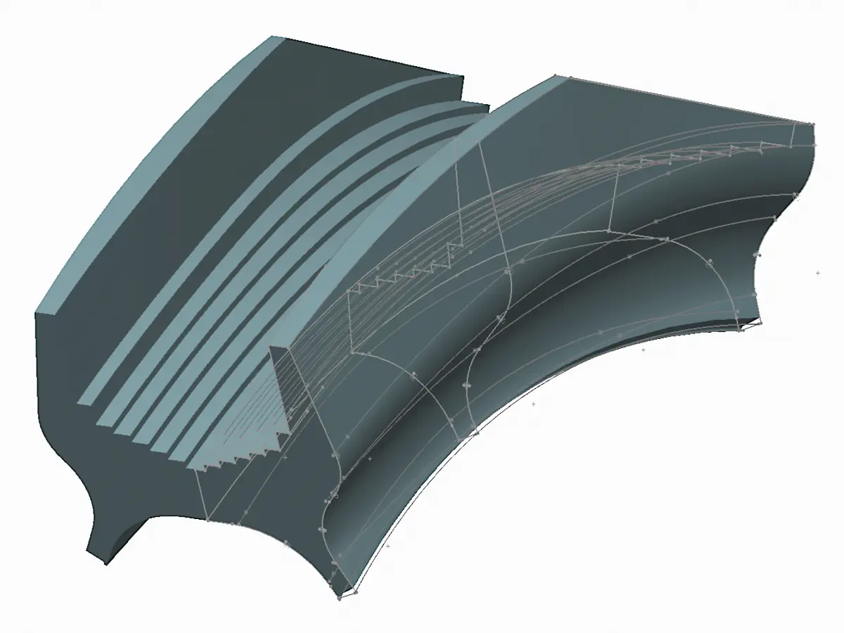
3D CAD model of a suspension bridge saddle developed for a bid-stage package
Situation
A structural castings manufacturer was working on a live bid for a major suspension-bridge project and needed proposal-stage design content for a family of large saddles and associated components.
Frugal was brought in to review a substantial set of structural engineer’s reference drawings, digest the geometry and interface requirements they implied, and develop fully detailed 3D models plus proposal drawings robust enough to support internal engineering review, costing, and manufacturing planning ahead of contract award.
The real problem
The real problem was turning a large and technically dense drawing set into a clean, dependable, production-relevant CAD package. The structural engineer’s drawings established the intended geometry and interfaces, but the manufacturer still needed those requirements translated into coordinated casting, fabrication and machining models suitable for bid-stage review.
The work sat at the complex end of CAD design services: precision-engineered cast, machined and welded interfaces, with the models structured to support foundry, fabrication, machining and costing review. This required careful interpretation of the references that drove the saddle geometry, clear definition of the cast, proof and finish states, and early resolution of welded features, fabricated elements and assembly interfaces.
Constraints
Complex drawing interpretation: A large drawing set from the end-client’s structural engineer had to be correctly interpreted before the geometry could be turned into production-relevant CAD.
Manufacturing-level model accuracy: The geometry had to be accurate and stable enough to support real manufacturing confidence, not just bid visuals.
Multiple configuration states: Each saddle had to be developed across cast, proof, and finish states, with matching drawing content and assembly context.
Interface risk had to be surfaced early: Associated fabricated steelwork and welded features had to be included so hidden clashes, constraints, and cost drivers could be identified before delivery.
Internal engineering scrutiny: The outputs needed to stand up to review by the client’s expert in-house engineering team, and support bid-stage costing and manufacturing assessment.
Client:
Structural castings manufacturer
Role:
Mechanical engineering consultant
Period:
2013
Scope:
Complex CAD design services +
Precision mechanical design +
Cast / weld / machine definition +
Proposal drawing pack
Acceptance basis:
Client design basis +
Client engineering review +
Bid-stage manufacturability
Key moves
Interpreting the structural engineer's drawings
- Reviewed the structural engineer’s reference drawings to identify the geometry-driving references, key interfaces, and production requirements relevant to the new saddles.
- Translated that information into a clean CAD basis for foundry, fabrication, machining and costing review.
Building clean, stable, fully detailed 3D models
- Developed fully detailed SolidWorks 3D models using concise, robust feature structures driven by key construction geometry established early in the model tree.
- Captured the complex swept, lofted, and machined geometries accurately, whilst keeping the models light, stable and usable for downstream drawing production.
Defining every manufacturing state
- Included cast, proof, and finish machining configurations within each model so the 3D models included all stages of geometry from foundry output to fully machined and fabricated component.
- Structured the package around production-relevant states and interfaces, so it could support review of casting, welding, machining, and assembly logic rather than only a single finished-shape model.
Incorporating fabrication and interfaces
- Included associated fabricated steelwork, welded features, and surrounding interface conditions so that how the saddles would really be built and installed was a part of the models from the outset.
- Used that fuller package to surface problem geometry, hidden constraints, and potential cost drivers early rather than leaving these to emerge later during delivery.
Working with in-house specialists
- Worked alongside the client’s welding engineer to develop practical welded-joint solutions for castings too large or impractical to remain single-piece castings.
- Produced a technically detailed package suitable for review by the client’s internal engineering team and for use in bid-stage manufacturing assessment.
Producing a bid-ready technical package
- Delivered proposal drawings for each saddle type and production state, together with general-arrangement content showing how the components would be assembled and interfaced.
- Gave the client a technically credible package that supported bid submission, manufacturing review, and more reliable material and weld-quantity costing.
Selected snapshots
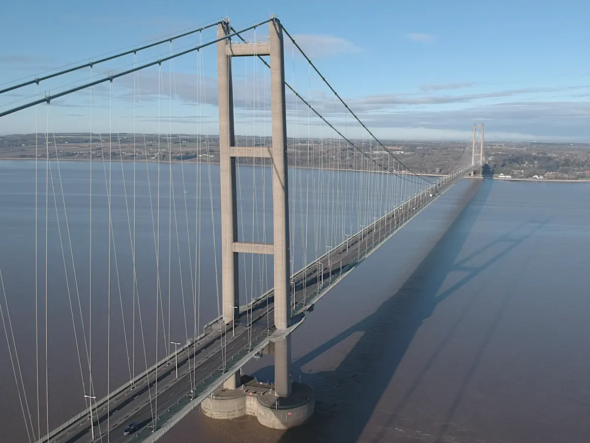
Indicative context image showing the type and scale of bridge involved
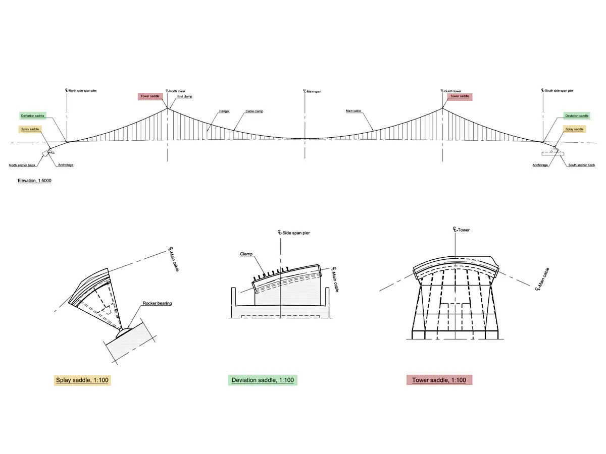
Indicative diagram showing the location of the saddle casting types within the wider bridge arrangement
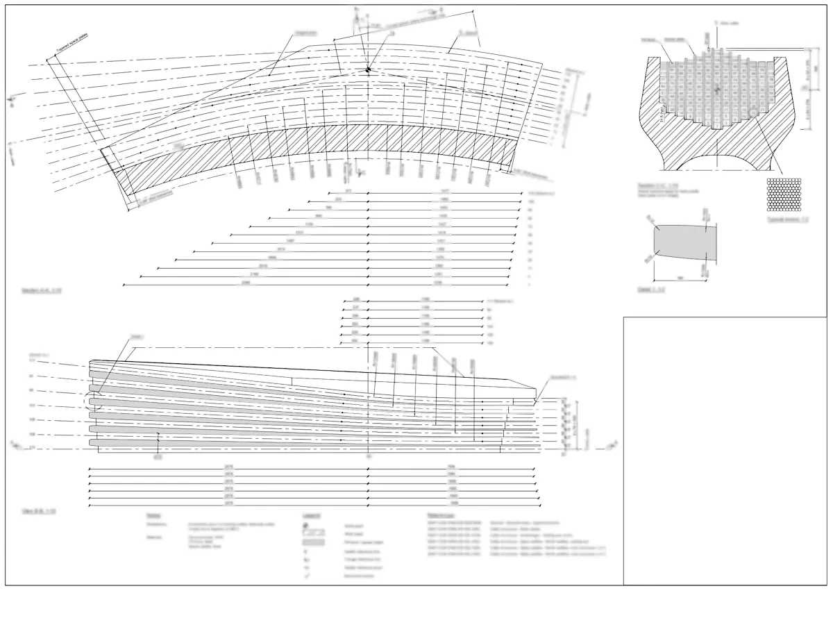
Around 40 structural reference drawings informed the work, of which this is an anonymised typical example
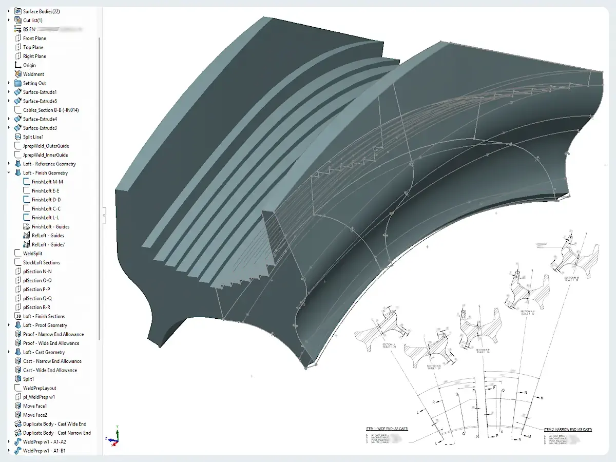
One of the fully detailed 3D part models, with some of the driving sketches left visible
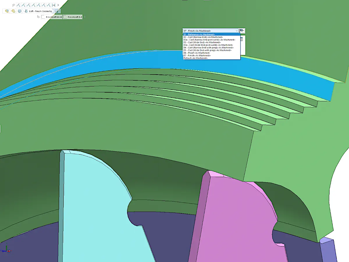
A multi-body part model showing production-state geometry and fabricated-component detail

One of the saddle assemblies, highlighting the level of production-relevant detail included in the 3D model

A typical example of the manufacturing drawing output included in the circa 25-sheet A1 drawing pack
Outcome
Frugal delivered a fully detailed 3D and drawing package covering the main saddle types as precision-engineered mechanical assemblies, including their production-relevant states, associated fabricated features, general arrangements and selected component-detail drawings.
This gave the client a coordinated technical package for internal engineering review, costing and assessment of the proposed manufacturing route.
What this enabled
The package gave the client a developed technical basis for the bid, allowing foundry, fabrication, machining and costing discussions to proceed from coordinated, production-relevant models rather than the structural reference drawings alone.
By defining production states, welded interfaces, fabricated elements and assembly relationships at bid stage, the work reduced uncertainty around the proposed manufacturing route and exposed material, interface and cost drivers before contract delivery.
Got an engineering design problem to solve?
Tell me what you're dealing with and I'll let you know whether I can help.